|
|
These photos show the ASSEMBLY because the parts (& my hands) are cleaner, so it's easier to see what's happening. Just start at the other end of this photo album for disassembly. It may help to switch the album view to Large Images with Captions & Links.
|
|
|
 10 Swivel Seal.JPG | Hits: 1722 | Size: 72.08 KB | Posted on: 10/9/04 | Link to this image 10 Swivel Seal.JPG | Hits: 1722 | Size: 72.08 KB | Posted on: 10/9/04 | Link to this image
Be sure to slip on the swivel ball seal & retainer before installing the swivel ball on the axle tube. The axle seal should already be installed in the back of the ball, and the paper gasket is on the flange.
|
|
|
 11 Swivel Ball.JPG | Hits: 1739 | Size: 78.89 KB | Posted on: 10/9/04 | Link to this image 11 Swivel Ball.JPG | Hits: 1739 | Size: 78.89 KB | Posted on: 10/9/04 | Link to this image
A ratcheting 13mm box end wrench is best for these bolts.
|
|
|
Preinstall the bottom pin & weight on the knuckle, using a new gasket. The screws have T-40 heads.
|
|
|
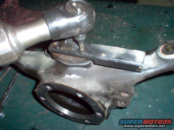 20 Bottom Screw.JPG | Hits: 1440 | Size: 76.44 KB | Posted on: 10/9/04 | Link to this image 20 Bottom Screw.JPG | Hits: 1440 | Size: 76.44 KB | Posted on: 10/9/04 | Link to this image
Tighten the screws fully. Note that the tab on the weight is AWAY from the spindle surface.
|
|
|
 21 Bottom Bearing.JPG | Hits: 1554 | Size: 80.78 KB | Posted on: 10/9/04 | Link to this image 21 Bottom Bearing.JPG | Hits: 1554 | Size: 80.78 KB | Posted on: 10/9/04 | Link to this image
With the bearing on the pin, slip the knuckle onto the ball & put the large seal in place.
|
|
|
 22 Swivel Retainer.JPG | Hits: 1493 | Size: 74.18 KB | Posted on: 10/9/04 | Link to this image 22 Swivel Retainer.JPG | Hits: 1493 | Size: 74.18 KB | Posted on: 10/9/04 | Link to this image
Tighten the 8mm screws. The retainer only fits one way.
|
|
|
This probably isn't necessary, but it gets grease settled into the bottom of the knuckle faster than putting it all in from the top later.
|
|
|
Prelube the CV, then work it around so the grease goes inside, then install the shaft assembly thru the knuckle.
|
|
|
The ABS seal is probably the most overlooked seal, but it seems to be a MAJOR source of leaks, judging by the amount of grime on the brake line bracket.
|
|
|
Use WABCO white grease here.
|
|
|
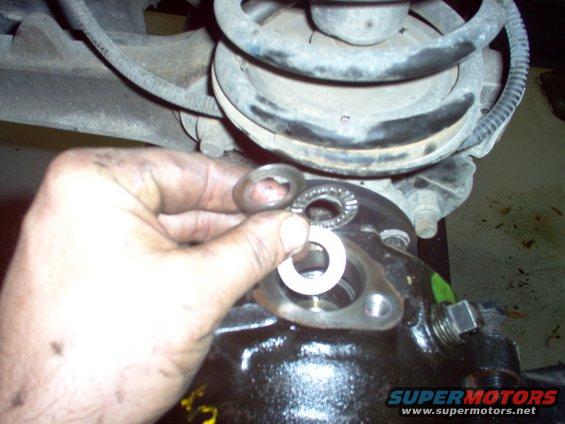 31 Top Bearing.JPG | Hits: 1446 | Size: 77.53 KB | Posted on: 10/9/04 | Link to this image 31 Top Bearing.JPG | Hits: 1446 | Size: 77.53 KB | Posted on: 10/9/04 | Link to this image
Drop in the lower thrust washer & the thrust bearing, making sure they rest properly.
|
|
|
 32 Top Prelube.JPG | Hits: 1487 | Size: 72.26 KB | Posted on: 10/9/04 | Link to this image 32 Top Prelube.JPG | Hits: 1487 | Size: 72.26 KB | Posted on: 10/9/04 | Link to this image
It's important to lube the bearing since it can take some time before the grease moves up here from the swivel ball.
|
|
|
Drop in the upper thrust washer, align the knuckle to the ball, and insert the top pin with shims. If you think there's a LOT of slop in the lower bearing, remove the thinnest shim you have.
|
|
|
 4 Spindle Bearing.JPG | Hits: 1521 | Size: 76.34 KB | Posted on: 10/9/04 | Link to this image 4 Spindle Bearing.JPG | Hits: 1521 | Size: 76.34 KB | Posted on: 10/9/04 | Link to this image
Use a slide hammer with the special adapter to pull the spindle bearing.
|
|
|
 40 Spindle Seal.JPG | Hits: 1574 | Size: 54.14 KB | Posted on: 10/9/04 | Link to this image 40 Spindle Seal.JPG | Hits: 1574 | Size: 54.14 KB | Posted on: 10/9/04 | Link to this image
Pry out the spindle seal.
|
|
|
 41 Spindle Seal.JPG | Hits: 1393 | Size: 73.5 KB | Posted on: 10/9/04 | Link to this image 41 Spindle Seal.JPG | Hits: 1393 | Size: 73.5 KB | Posted on: 10/9/04 | Link to this image
The new seal can be pushed in by hand, or with a drift. The metal ring faces up.
|
|
|
 42 Spindle Bearing.JPG | Hits: 1577 | Size: 51.56 KB | Posted on: 10/9/04 | Link to this image 42 Spindle Bearing.JPG | Hits: 1577 | Size: 51.56 KB | Posted on: 10/9/04 | Link to this image
Use a drift to set the bearing back in. If it's not damaged, it can be reused.
|
|
|
Using a new gasket, reinstall the spindle & the ring. I prefer the flat facing up, but the rear hubs have it facing front. I don't think it matters.
|
|
|
Finish adding the grease & reinstall the plug.
|
|
|
Set the brake line bracket back in place with both bolts & tighten the front bolt first using a 17mm ratcheting box end. A socket will reach the rear bolt.
|
|
|
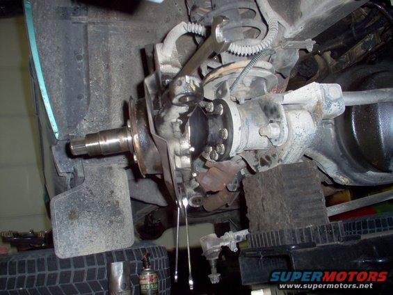 50 Shield Bolts.JPG | Hits: 1399 | Size: 85.87 KB | Posted on: 10/9/04 | Link to this image 50 Shield Bolts.JPG | Hits: 1399 | Size: 85.87 KB | Posted on: 10/9/04 | Link to this image
Reinstall the brake shield, using a 19mm for the stop bolt's nut, & an 8mm and 10mm for the bottom.
|
|
|
Push the ABS sensor FULLY into place.
|
|
|
Reinsert the tie rod ends into the steering knuckle, making sure the holes point directly outward. Tighten the 19mm castellated nuts so a cotter pin can be inserted. With the pin going in this way, it will be easier to remove later. It's not necessary to mangle the pin or wrap it fully. Keeping the bends simple will make it easier to straighten & remove later.
|
|
|
Pull the hub seal, remove & clean the wheel bearings.
|
|
|
 6 Bearing Grease.JPG | Hits: 1475 | Size: 69.74 KB | Posted on: 10/9/04 | Link to this image 6 Bearing Grease.JPG | Hits: 1475 | Size: 69.74 KB | Posted on: 10/9/04 | Link to this image
Repack the wheel bearings by whatever method you can. This tool is reasonbly-priced on Amazon & eBay, and makes this job nearly clean. Using needle-nose pliers to transfer the packed bearing from the tool to the hub significantly reduces cleanup time.
|
|
|
Drop in the inner wheel bearing & install a new hub seal. Note that it should be recessed in the hub. The white plastic disk is the special tool.
|
|
|
Fill the area between the bearing races with grease. This prevents the bearings from throwing their grease out, and reduces the amount of air inside the hub, which reduces its tendency to suck in water during fording.
|
|
|
Install the rotor, using anti-sieze lubricant where it presses onto the hub, and on the bolts. The heads are 12-point 14mm.
|
|
|
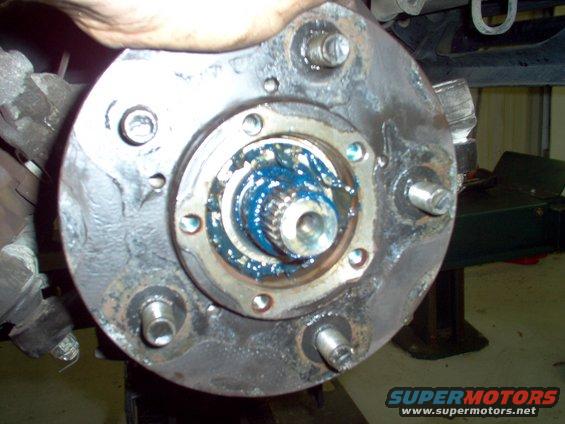 7 Outer Bearing.JPG | Hits: 1526 | Size: 79.67 KB | Posted on: 10/9/04 | Link to this image 7 Outer Bearing.JPG | Hits: 1526 | Size: 79.67 KB | Posted on: 10/9/04 | Link to this image
Slide the assembled hub & rotor (yes, I forgot it & had to backtrack) onto the spindle, followed by the packed outer bearing. These bearings will never run dry, and if a small amount of water gets inside, it's unlikely it will ever contact the bearings.
|
|
|
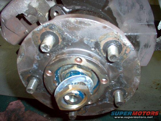 70 Spindle Nut.JPG | Hits: 1619 | Size: 79.16 KB | Posted on: 10/9/04 | Link to this image 70 Spindle Nut.JPG | Hits: 1619 | Size: 79.16 KB | Posted on: 10/9/04 | Link to this image
Install the thick washer and set the inner nut by hand while rotating the hub. Then install the lock ring & the outer nut.
The rotor should have been on the hub already. I had to backtrack later.
|
|
|
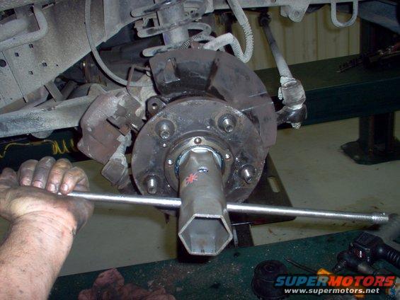 71 Spindle Socket.JPG | Hits: 1589 | Size: 79.44 KB | Posted on: 10/9/04 | Link to this image 71 Spindle Socket.JPG | Hits: 1589 | Size: 79.44 KB | Posted on: 10/9/04 | Link to this image
Set the outer nut as tight as you can.
The rotor should have been on the hub already. I had to backtrack later.
|
|
|
Fold the lock ring outward over a flat of the outer nut & hammer it tight & flat.
The rotor should have been on the hub already. I had to backtrack later.
|
|
|
Look past the folded area to see where the inner nut's flats are, and fold the ring inward over one of them. Reinstall the caliper, brakes, drive flange, & stub axle snap-ring and dust cap.
The rotor should have been on the hub already. I had to backtrack.
|
|
|