|
|
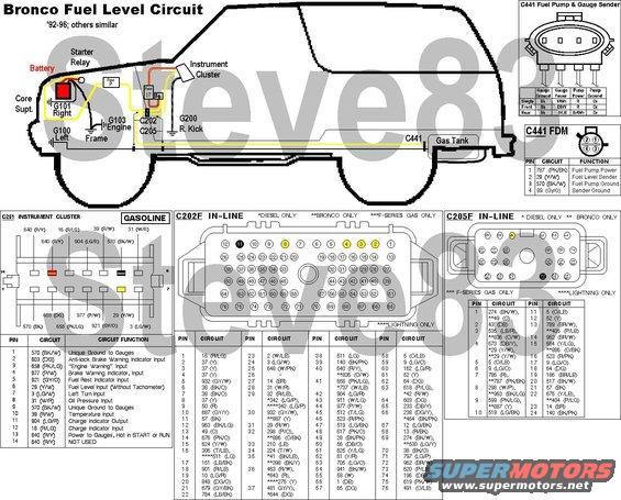
 FuelLevelWiring.JPG | Hits: 23080 | Size: 78.84 KB | Posted on: 7/19/09 | Link to this image FuelLevelWiring.JPG | Hits: 23080 | Size: 78.84 KB | Posted on: 7/19/09 | Link to this image
Fuel Level Sender & Gauge Wiring for '92-96 Broncos ('87-91 Bronco similar) IF THE IMAGE IS TOO SMALL, click it. For '87-96 F-series w/dual tanks, see:  ERROR: C251 pin 5 should read "Fuel ResEt Indicator Input", but that circuit is not present on most trucks, and not used on any. There may be other errors or variations due to model year changes & optional equipment. Sender Range: 160 (full) - 16 (empty) Ohms A gauge that pegs past full indicates an open circuit on the Y/W wire (broken wire; unplugged connector; corroded terminal; varnished sender; F-series - selector switch or connector faults). A gauge that pegs past empty indicates a short to ground on the Y/W wire (pinched to the frame, body, or dash supports), a fault in the gauge or its power or ground from the film circuit, OR a sunken float. A gauge anywhere in between that doesn't move indicates an open circuit (blown fuse; corroded terminal) on the power (battery) side of the gauge OR a bad instrument cluster ground at C251 pin 9 (both of which would affect MORE of the cluster than strictly the fuel level gauge). To test it, ground the Y/Wh wire as close to the instrument cluster as possible, and turn the key to RUN. If the gauge instantly moves toward E, the gauge & its power/ground are good, and the fault is PAST where you grounded the Y/Wh wire. If not, the fault is BEFORE that point, in the gauge, cluster, or power/ground wiring. The terminals of C251 (& C250) are known to corrode & lose contact (open), which would cause the gauge to read high or peg past Full. Polish both the connector pins AND the film circuit pads with brown paper or a pink eraser.  .  The larger/older version of C441(WPT454) was used until '93.  .  .  A medium-sized connector was used from '93-95. The level sender can usually be disassembled & repaired by bending the wiper arm inside the plastic housing to apply slightly more force. See the other photos in this album. For more info, see these albums' captions:  .  .  .  -Bronco ONLY-  See also: MotorCraft 2016 Wiring Pigtail Guide
|
|
|
As much of an improvement as the FDM system was over the previous EFI pump system, it's still subject to failures, mostly related to fuel varnish building up on its internal surfaces. When it builds up in the level sender, it causes the gauge to peg FULL, as any open circuit would (high resistance). If diagnosis shows the fault to be inside the tank, the sender can sometimes be cleaned & returned to service for a fraction of the cost of a new sender. In either case, a new O-ring is required between the pump mounting plate & the tank. Instructions for removing the FDM can be found in these albums' captions:  .  -Bronco ONLY See also:  .  . 
|
|
|
Pry the float arm out of the sender clip, being careful not to break the plastic. Prying between the clip & the pivot hole is the most-effective method, and a drop of clean motor oil on the clip will make it easier.
Clean motor oil is the ONLY approved lubricant for inside the fuel system, and it's very effective.
|
|
|
Remove these two 1/4" screws and the one below the sender (LEFT in the photo), leaving the one that holds the FDM to the hard lines above the sender.
|
|
|
Flip the sender for access to its clips.
|
|
|
Cut off the melted peg(s).
|
|
|
Release the catch and slide the plastic housing off the metal plate.
To make reassembly easier, trim the peg that was cut off so it does NOT engage the plate.
|
|
|
The wiper arm is loose inside the sender housing, without the float arm to hold it. The rheostat board snaps into the housing. It's easy to remove by easing out the long catches, but be careful to feed the Y wire through so it's not ripped off the board. If it breaks free, solder it back on.
|
|
|
To clean the board, I use #000 steel wool; for the brass wiper contacts, 400gr. emery paper. After polishing the brass, gently bend it so it applies SLIGHTLY more force to the board & the stainless mounting plate (ground).
|
|
|
This is the board before cleaning...
|
|
|
...this is after. DO NOT CLEAN the green areas since they provide the necessary resistance, and any cleaning can permanently change that. Note most of the black corrosion between the traces is gone. If the traces are damaged or corroded, the sender must be replaced. So far, about half the senders I've cleaned have worked afterward. 
|
|
|
Polish the mating surfaces between the hard tubes' plate (still screwed to the FDM) and the sender backing plate so the sender has a good ground path.
|
|
|
Polish the area around the float arm pivot hole where the brass wipers will touch.
|
|
|
After reassembling the rheostat board, sender housing, wiper arm, & backing plate, press the arm back into the wiper clip. It may be necessary to lubricate the clip with clean motor oil so the rod can slide in more easily. NEVER use any other lubricant in the fuel system, ESPECIALLY NOT silicone grease. Make sure the rod is aligned with the hole in the plate before forcing it into the clip.
|
|
|
Finally, check the sender's output over the full range, making sure it produces a smooth continuous signal from ~16~160 Ohms. If not, replace it.  Broncos & front tanks use a hollow brass float as shown. (F-series rear tanks use a solid foam float.) If liquid can be heard splashing inside, or if the float remains wet with fuel, it should be replaced. But with EXTREME care, it can be emptied, polished, and the leaks soldered shut with a common electronics soldering iron & rosin-core solder. To test it for leaks, put it in a freezer for ~5min, then quickly submerge it in HOT water. Bubbles will emanate from the main leaks. Repair & repeat testing until all leaks have been stopped, and the float is empty. New replacements are inexpensive & common, but hollow floats are inherently UNreliable.  Aftermarket hollow plastic floats are also available, but a foam float is vastly superior. 
|
|
|
Fuel Floats IF THE IMAGE IS TOO SMALL, click it.  .  . 
|
|
|
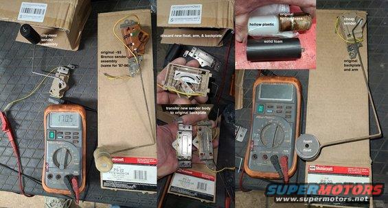
 LevelSenderRebuild.jpg | Hits: 890 | Size: 58.18 KB | Posted on: 2/17/22 | Link to this image LevelSenderRebuild.jpg | Hits: 890 | Size: 58.18 KB | Posted on: 2/17/22 | Link to this image
Since genuine level senders aren't available, imported copies will have to do. Fortunately, it's cheap & easy to swap virtually any '87-04 level sender onto your existing tank hanger, using your existing arm & float. If your float is leaking (or hollow, with the potential to leak), it's easy to swap on a generic foam float, but usually, the float arm can simply be bent slightly to work with the included solid-foam float (regardless of shape).
IF THE IMAGE IS TOO SMALL, click it.
|
|
|
Level Sender Testing
IF THE IMAGE IS TOO SMALL, click it.
Before re-installing a sender in the tank, test gauge response in at least 3 positions; 5 are better. The time it takes to move from the rear to the driver's seat is probably NOT enough for the needle to slowly move, so give it a few minutes. It's specifically built NOT to move rapidly.
Read the rest of this photo album...
|
|
|