|
|
 autolockhubsd441996.jpg | Hits: 2220 | Posted on: 1/18/04
| View Low-Res
autolockhubsd441996.jpg | Hits: 2220 | Posted on: 1/18/04
| View Low-Res
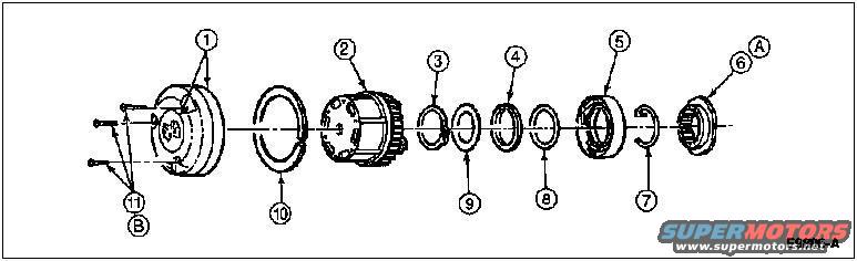
Auto Lock Hubs D44 1996
1 Cap, 2 Hub Body, 3 Snap Ring, 4 Plastic Thrust Washer, 5 Cam Assembly (Part of 1K105), 6 Wheel Retainer (Nut), 7 Wheel Retainer Key, 8 Steel Thrust Washer, 9 Splined Thrust Washer, 10 Lock Ring, 11 cap screws (3)
A. While Rotating Front Disc Brake Hub & Rotor, Tighten Wheel Retainer (Nut) to 68 N-m (50 Lb-Ft) to Seat Wheel Bearings. Back Nut Off 90 Degrees (1/4 Turn). Tighten to 1.8 N-m (16 Lb-In).
B. Tighten to 4-6 N-m (35-53 Lb-In)
Removal
1 Separate cap from body assembly by removing the three capscrews, using Torx� bit TX25 or equivalent, from the cap.
2 Remove cap.
3 Remove the lock ring seated in the groove of the front disc brake hub and rotor (1102).
4 Remove the body assembly from the front disc brake hub and rotor.
5 Remove C-washer or snap ring from stub shaft groove.
6 Remove spacers (three thrust washers) from shaft.
7 Remove cam assembly. Pull to remove.
8 If front disc brake hub and rotor and front wheel spindle (3105) are to be removed, refer to Wheel Grease Seal and Bearing, Front Replacement and Repacking in the Disassembly and Assembly portion of this section.
|