|
|
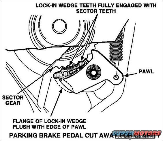
7. (continued) Using a hammer, drive the lock-in wedge between the pawl and the sector gear, until the flange of the wedge is flush with the edge of the pawl. NOTE: The drive surface of the wedge is where the head of the punch must be placed during installation of the wedge.
8. Verify that the lock-in wedge is fully seated. Wedge teeth must be fully engaged with at least one of the sector teeth. Wedge flange must be flush with the edge of the pawl.
|