|
|
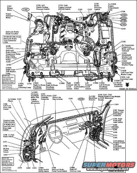 Connector 1994 View.jpg | Hits: 3597 | Size: 96.47 KB | Posted on: 2/6/05 | Link to this image Connector 1994 View.jpg | Hits: 3597 | Size: 96.47 KB | Posted on: 2/6/05 | Link to this image
1994 Connectors
|
|
|
 Connector 1994.jpg | Hits: 2354 | Size: 45.11 KB | Posted on: 2/13/05 | Link to this image Connector 1994.jpg | Hits: 2354 | Size: 45.11 KB | Posted on: 2/13/05 | Link to this image
1994 Connector Pinouts
|
|
|
I've collected a few cop PCMs to test when I get the engine installed, and I'll probably keep one spare & sell one.
Ultimately, I went with the '99 P71 ARA3. It has the sportiest ignition curves & shift points.
|
|
|
1994 Dash harness (14401) connectors
|
|
|
1994 Dash harness (14401) connectors
|
|
|
1994 Dash harness (14401 & 12614) connectors
|
|
|
1994 Dash harness (14401 & 12614) connectors
|
|
|
1994 Engine bay harness (14290) connectors
|
|
|
1994 Engine bay harness (14290) connectors
|
|
|
1994 Engine bay harness (14290) connectors
|
|
|
1994 Engine bay harness (14290) connectors
|
|
|
1994 Engine bay harness (14290) connectors
|
|
|
1994 EEC harness (12A581) connectors
|
|
|
1994 EEC harness (12A581) connectors
|
|
|
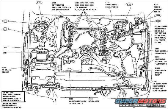 Connector 2000 View.jpg | Hits: 2360 | Size: 79.83 KB | Posted on: 2/6/05 | Link to this image Connector 2000 View.jpg | Hits: 2360 | Size: 79.83 KB | Posted on: 2/6/05 | Link to this image
2000 Connectors
The circled ones are what I have to splice onto the '94 dash harness.
|
|
|
 25 BayLConnectors.JPG | Hits: 1355 | Size: 54.05 KB | Posted on: 2/6/05 | Link to this image 25 BayLConnectors.JPG | Hits: 1355 | Size: 54.05 KB | Posted on: 2/6/05 | Link to this image
2000 Engine bay harness (14290) connectors
|
|
|
 26 BayLConnectors.JPG | Hits: 1335 | Size: 52.31 KB | Posted on: 2/6/05 | Link to this image 26 BayLConnectors.JPG | Hits: 1335 | Size: 52.31 KB | Posted on: 2/6/05 | Link to this image
2000 Engine bay harness (14290) connectors
|
|
|
 27 BayRConnectors.JPG | Hits: 1486 | Size: 47.85 KB | Posted on: 2/6/05 | Link to this image 27 BayRConnectors.JPG | Hits: 1486 | Size: 47.85 KB | Posted on: 2/6/05 | Link to this image
2000 Engine bay harness (14290) connectors
|
|
|
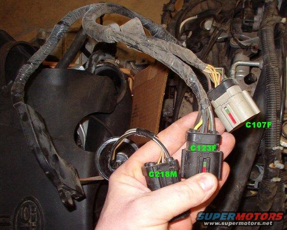 28 BayRConnectors.JPG | Hits: 1409 | Size: 59.67 KB | Posted on: 2/6/05 | Link to this image 28 BayRConnectors.JPG | Hits: 1409 | Size: 59.67 KB | Posted on: 2/6/05 | Link to this image
2000 Engine bay harness (14290) connectors
|
|
|
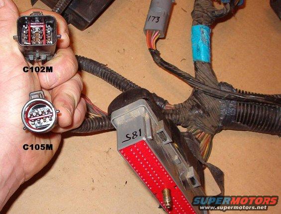 29 EECConnectors.JPG | Hits: 2150 | Size: 57.96 KB | Posted on: 2/6/05 | Link to this image 29 EECConnectors.JPG | Hits: 2150 | Size: 57.96 KB | Posted on: 2/6/05 | Link to this image
2000 EEC harness (12A581) connectors
|
|
|
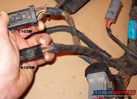 30 EECConnectors.JPG | Hits: 1461 | Size: 56.41 KB | Posted on: 2/6/05 | Link to this image 30 EECConnectors.JPG | Hits: 1461 | Size: 56.41 KB | Posted on: 2/6/05 | Link to this image
2000 EEC harness (12A581) connectors
|
|
|
 Spreadsheet temp.jpg | Hits: 2073 | Size: 88.64 KB | Posted on: 2/13/05 | Link to this image Spreadsheet temp.jpg | Hits: 2073 | Size: 88.64 KB | Posted on: 2/13/05 | Link to this image
List of circuits, pins, & necessary mods. Pins not listed are empty on the harnesses I have. All modifications will be done on the 94 harnesses so the 00 harnesses will simply plug in. In the L column, blue indicates the pin must be cut off for either gender or size change; pink means the wire must be extended from the L side of the dash to the R side; green is opposite. JOIN means there will be a Y splice.
|
|
|
I bought a wide variety of colors & sizes of wire to try to mimic factory colors as closely as possible.  Later, I found even more colors & a few stripe options on eBay for less money than these cost locally.
|
|
|
Turns out I had to pull the dash to continue with rewiring. I wanted to avoid it, but it was easier than I expected.
|
|
|
Turns out I had to pull the dash to continue with rewiring. I wanted to avoid it, but it was easier than I expected.
|
|
|
Turns out I had to pull the dash to continue with rewiring. I wanted to avoid it, but it was easier than I expected.
|
|
|
I set the dash on the front of the car to work on the wiring.
|
|
|
I set the dash on the front of the car to work on the wiring.
|
|
|
Several circuits have to be added across the dash, and some are deleted.
|
|
|
FINISHED!!! ...with the R side of the dash harness where it enters the engine bay.
|
|
|
The remote starter installation will be cleaned up now.
|
|
|
The L dash wiring is almost finished.
|
|
|
Most of the wiring is cleaned up & covered with split loom. The blue wires are some spares fed by engine compartment fuses that I'll probably use for a floor console or small amplifier later.
|
|
|
The RKE/start wiring has been soldered in (with a few minor modifications) and the FTP & CANV wires run thru the connectors in the lower L. The RKE antenna will be placed much better along the windshield (small yellow wire in the lower center).
|
|
|
The RKE barely fits under the autolamp module. The wires that run under the steering column area were placed there before I knew the dash had to come out, and now it's too late to reroute them.
|
|
|
Everything is finished & tucked in so the dash can be reinstalled without pinching any wires.
|
|
|
Everything is finished & tucked in so the dash can be reinstalled without pinching any wires.
|
|
|
Everything is finished & tucked in so the dash can be reinstalled without pinching any wires.
|
|
|
I repaired all the cuts from the original RKE installation, but some of those taped locations are from rearranging the ignition switch circuits to balance the loads for the new power feeds from the 2000 engine bay wiring.
|
|
|
Everything is finished & tucked in so the dash can be reinstalled without pinching any wires. The purple wires near the headlight switch are for the RKE dome light management relay (which is out of sight under the headlight switch), and the thin yellow wire on top is the RKE antenna, which will be taped to the A-pillar beside the windshield.
|
|
|
The new branch off the firewall harness with the white plug is the RKE wiring into the lock circuit. It will plug into the module below the autolamp sensor.
|
|
|
The new branch off the firewall harness with the white plug is the RKE wiring into the lock circuit. It will plug into the module below the autolamp sensor.
|
|
|
The purple wire is the RKE trigger for the trunk release; the orange is for a future outside temp sensor for the rear-view mirror; and wires were added to these connectors & run under the carpet for the FTP & CANV.
|
|
|
Some wires in these connectors were rearranged, and the Bk/Wh wire is a main power feed that will tie into the dash harness.
|
|
|
The dash is finally going back in. Its harness on the R side is visible just below the paddle-shaped brace.
|
|
|
The dash harness reaches the engine bay connectors better than I thought, considering I used many wires without lengthening them.
|
|
|
The L side dash harness being pulled thru.
|
|
|
Even though not equipped, this harness is wired for Illuminated Entry & power antenna.
|
|
|
My odo: 187437
Donor's: 070020
UPDATE: 10/7/8
My odo stopped working shortly after the swap and I drove maybe 2 years without it, so I've lost track of how many miles are on the engine/trans now.
|
|
|
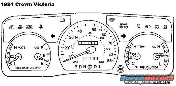 InstCluster94CV.jpg | Hits: 1879 | Size: 43.12 KB | Posted on: 5/11/05 | Link to this image InstCluster94CV.jpg | Hits: 1879 | Size: 43.12 KB | Posted on: 5/11/05 | Link to this image
My cluster actually says "Low Coolant" where this diagram shows "Check Temp".
|
|
|
 InstClusterBulbs94CV.jpg | Hits: 1732 | Size: 63.1 KB | Posted on: 5/11/05 | Link to this image InstClusterBulbs94CV.jpg | Hits: 1732 | Size: 63.1 KB | Posted on: 5/11/05 | Link to this image
Cluster Bulbs '94
|
|
|
To make the gauge work with a real oil pressure sender, solder a jumper wire across the 20 Ohm resistor. I used a Wh/R wire because that's what the oil sender circuit is.
|